

A pergola installation can stall even when the structure itself is ready. The usual gap is not a missing “how to build” tutorial; it is an incomplete handover between the buyer, pergola supplier, local designer, site contractor and installer.
This pergola installation handover checklist is for project buyers who want those interfaces agreed before the installation team arrives. It does not replace project drawings, local approvals, engineering review, product instructions or a competent installer’s method statement.
Editorial boundary: Prepared and reviewed by the Oscar Pergola editorial team using current Oscar project references and public U.S. safety and permitting guidance. Dimensions, foundations, anchors, permits, electrical work and installation methods remain project-specific and must be approved by the responsible local professionals.
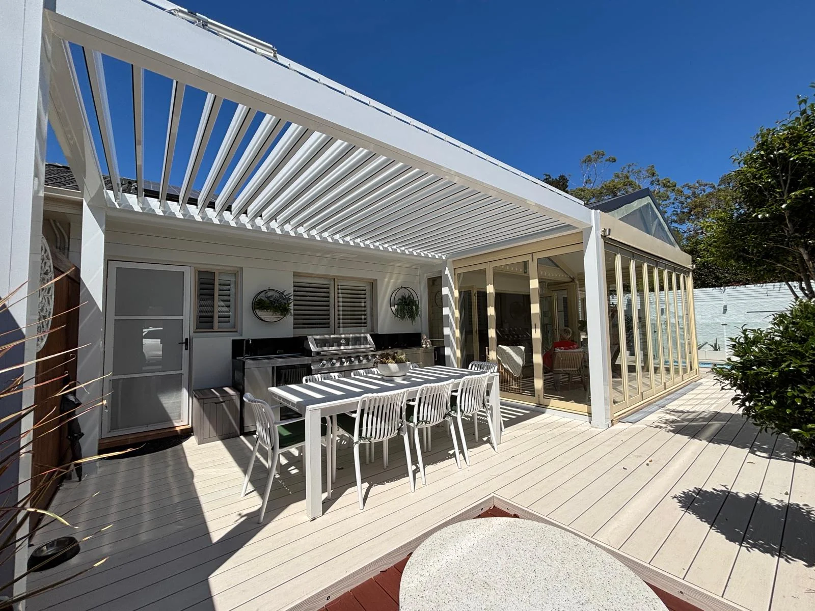
1. Freeze one approved installation package
Do not let the quotation, sales sketch, production drawing and installer copy become four different versions. Before dispatch, the project lead should identify one approved package and record its revision date. At minimum, the package should show the pergola footprint, elevations, column positions, roof orientation, drainage outlets, attachment points and selected options.
- Approved general arrangement and relevant elevations.
- Component and fastener identification that matches the delivered labels or packing information.
- Supplier-issued assembly information and any project-specific deviations.
- Interfaces for motors, screens, lighting, sensors, drainage and building attachment.
- A named contact and written question process for installation conflicts.
If a later revision changes a column, outlet or fixing point, withdraw the older copy rather than expecting the installer to notice the difference.
2. Reconcile the drawing with the actual site
A site photograph is useful, but it does not prove dimensions, levels or substrate capacity. Record the finished opening, height constraints, wall and door positions, property boundaries, existing drainage, slopes, service routes and access for tools and components. For an attached layout, confirm the exact building interface; for a freestanding layout, confirm every column center and the supporting construction below it.
Do not assume an existing slab, deck, wall or footing is suitable just because it looks substantial. The responsible local engineer or other qualified professional should verify the support and fixing design for the actual loads, substrate and jurisdiction. Any mismatch between the approved drawing and the site is a request for information, not permission to improvise.
3. Confirm permits, design review and inspections locally
Permit rules are not universal. For example, the City of Boulder’s accessory-structure guide describes a limited permit exemption for some small pergolas while still requiring applicable code and setback compliance. The City of Round Rock’s homeowner project guidance asks for items such as plans, a marked property survey and electrical or plumbing details when applicable.
Those examples demonstrate why a buyer should not copy another city’s threshold. Ask the authority having jurisdiction which planning, building, electrical, drainage, heritage, fire, pool-area or homeowners-association approvals apply. Record who provides the drawings, who signs or stamps them when required, who books inspections and what must remain visible for inspection.
4. Clear underground and concealed services before work
Column foundations, anchors and incoming electrical routes can conflict with buried or concealed services. In the United States, 811 provides the national route to the relevant state notification center before digging; the required notice period and process depend on the state. Projects elsewhere should use the applicable local utility-location service.
Utility marks do not replace the installer’s site assessment. Also check private services, irrigation, drainage, slab heating, post-tensioned concrete, waterproofing membranes and building services that may not be covered by a public locate. Put confirmed no-drill and no-excavation zones on the installer’s drawing.
5. Assign each installation interface to one owner
| Interface | Responsible party to name | Evidence required before mobilization |
|---|---|---|
| Approved layout and supplied components | Pergola supplier and project lead | Revision-controlled drawing, component list and selected-option schedule |
| Site measurements and existing construction | Buyer’s surveyor, contractor or installer | Recorded dimensions, levels, photographs and substrate description |
| Structural support and anchors | Qualified local designer or engineer where required | Project-specific detail accepted for the actual support |
| Permits and inspections | Named permit applicant or contractor | Approval status, inspection sequence and conditions |
| Electrical and controls | Qualified local electrical installer | Supply, protection, cable route, control and testing plan |
| Unloading, lifting and temporary works | Installation contractor | Site-specific method, equipment plan and competent supervision |
| Final acceptance | Buyer or project lead | Commissioning record, defects list and handover documents |
A name is more useful than “by others.” If responsibility is shared, state who supplies information, who reviews it and who gives final approval.
6. Plan delivery, storage and lifting as site work
Confirm vehicle access, unloading location, component lengths, storage protection, lifting space and the sequence in which packages must be opened. Keep the receiving check separate from the installation method: use the pergola delivery inspection checklist to reconcile packages and visible condition before parts are distributed around the site.
The supplier can provide component information, but the installation contractor must plan safe handling for the real site. In the United States, OSHA’s construction rigging standard requires covered rigging equipment to be inspected and identified with its recommended safe working load. This article does not prescribe lifting equipment or technique; those decisions belong in the competent contractor’s site-specific method.
7. Resolve fixing, drainage and weather interfaces
Before drilling or sealing, the installer should be able to identify the approved anchor location, embedment or connection detail, isolation between dissimilar materials, edge distances and any waterproofing or flashing interface. These details must come from the approved project design and product instructions, not from a generic article.
Trace the intended water path from the roof to every outlet and then to the site drainage point. Confirm that column outlets, building gutters, paving falls and underground connections do not conflict. Record which party supplies sealants, flashings, drains and field connections, together with the approved products and preparation requirements.
8. Coordinate power, controls and moving parts
Motorized louvers, screens, lighting and sensors create interfaces between the structure supplier and local electrical installer. Show cable entries, serviceable driver or controller locations, no-drill zones and the movement envelope of every component. The local installer must confirm supply, protection, grounding or bonding, wiring methods, permits and testing for the project location.
For the earlier ordering stage, combine this handover with Oscar’s motorised louvre pergola quote checklist. Do not accept “power by others” as the complete interface if nobody has agreed where the power arrives or who commissions the controls.
9. Define stop-and-check triggers
The installer should pause and raise a written question when any of the following appears:
- Site dimensions or levels do not match the approved drawing.
- A component, fastener or label is missing, damaged or inconsistent with the list.
- The proposed fixing point conflicts with an edge, service, membrane or unsupported construction.
- A field cut, hole, weld or substitution is proposed but is not shown in approved information.
- Drainage cannot follow the documented route.
- An electrical component, control or cable route differs from the coordinated plan.
Record the question, photographs, affected drawing reference, proposed response and approver. Verbal agreement alone is difficult to verify later.
10. Close the project with an installation record
Before final acceptance, collect the approved drawings, recorded changes, concealed-work photographs, commissioning results, operating instructions, maintenance access information and a list of unresolved defects. Keep product and component documents tied to the actual supplied configuration rather than a general catalogue.
What to send before requesting installation support
Send the project country, site address or jurisdiction, attached or freestanding layout, approximate dimensions, quantity, site photographs, support description, selected options and the identity of the local installer or designer. You can compare Oscar’s current pergola layouts, review the available project and customization services, and submit the project details for quotation review.
Final handover gate
- One current drawing package is identified and older revisions are withdrawn.
- Actual site dimensions, support and service conflicts are recorded.
- Local approvals, design responsibility and inspections have named owners.
- Delivery, lifting, fixing, drainage and electrical interfaces are documented.
- The installer has clear stop-and-check triggers and a written question route.
- Final commissioning and handover records have an agreed recipient.
A complete handover does not guarantee that every site condition is known in advance. It makes gaps visible early enough for the right party to resolve them before the installation team is forced to guess.